Circuit principle and installation of occlusion infrared detection alarm
In order to prevent thieves from entering the room, people usually install a fence outside the window. This method is the most common. In fact, this method seems to be neither beautiful nor has many drawbacks, because he does not automatically alarm. In the event of a fire, the fence will also cause the owner to be inside the room and be in danger. Accordingly, some engineers have specially designed an infrared detection and alarm device that can replace the traditional protective fence.
It can be applied to windows, doors and warehouses and other environments. Once the thief enters the protection zone to block the infrared light, it can automatically sound an alarm. The use of the device does not require a window to be closed, which saves a large expenditure on the installation of the guard rail, is economical and practical, and is also aesthetically pleasing.
This alarm device is used for the protection of the door and window of the residents. It can also be used for illegal intrusion. It can be arranged in various protection areas such as fences and corridors through array transceivers for residential boundary protection and large-area protection in residential buildings. If someone finds an illegal invasion (or stealing), it can automatically alarm. The system can be used alone or in a networked center to form a protective belt.
1. Circuit principle The circuit principle is shown in Figure 1. It consists of three parts: infrared transmitting and receiving device and alarm circuit. The core component of the circuit is an audio phase-locked loop integrated circuit LM567. The chip acts as both an oscillator and a frequency selective receiver in the circuit. The peripheral circuit is exceptionally simple and cost-effective. It is low-cost, easy to manufacture, no need to debug, and is not affected by voltage and temperature during work. It can work stably for a long time in various environments.
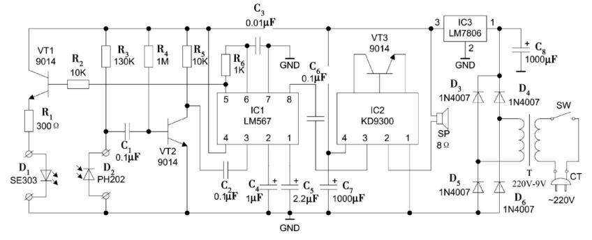
Occlusion type infrared detection alarm circuit diagram
At present, the infrared alarms appearing on the market are mostly composed of a modulation transmitter and an infrared receiving phase-locked demodulator. When making such a circuit, the frequency of the transmitter must be made consistent with the frequency of the demodulator, otherwise the control distance will be greatly shortened and the debugging will be troublesome. When the external voltage and temperature change, there is still a certain influence on the operating frequency, so the reliability is greatly reduced. In the engineer's design, both modulation and reception phase-locked demodulation use the same chip. The frequency of modulation transmission is the frequency of phase-locked demodulation. The transmission and reception always maintain the same frequency, which just overcomes the above shortcomings.
The internal structure of the phase-locked loop audio decoding integrated circuit LM567 is shown in Figure 1. It uses 8-pin dual in-line plastic package, working voltage is 4.75~9V, working frequency from DC to 500kHz, static working current is about 8mA. The internal circuit and detailed working process of LM567 are very complicated. Here are only the basic functions of the LM567: The internals of pins 5 and 6 of LM567 are a controllable voltage oscillator. The connected resistor R6 and capacitor C3 determine the internal voltage controlled oscillator. The center frequency f, f≈1/(1.1RC). The square wave oscillation signal generated by the 5 feet is amplified by VT1 and then the infrared emission tube VD1 is driven to emit an infrared pulse. After the infrared pulse is irradiated to VD2, a voltage pulse of the same frequency is generated at both ends, and the pulse is sent to the VT2 through C1. The base, and the inverter formed by the tube is inverted to form a square wave having the same waveform as the center frequency, and is input to the 3 pin of the LM567 via C2. Since the oscillation and phase-locked reception are the same oscillation source, the transmission frequency is the same as the center frequency. Pin 3 is the input of the LM567 and requires an input signal greater than 25mV. Pin 8 is the logic output of the LM567. The inside is an open-collector transistor that allows a maximum sink current of 100mA. When the LM567's 3-pin input amplitude is greater than 25mV and the frequency is within its bandwidth, the 8-pin output is low. At this time, there is no signal at the trigger end of the alarm music circuit, and the circuit will not alarm. When an object intercepts the infrared pulse, the 8-pin output immediately becomes a high level, and the level of the change is used to control the operation of the alarm circuit, so that the circuit emits an alarm sound. Composition - an "occlusion" infrared alarm. The infrared transmitting and receiving probes are generally installed in the concealed position of the H window. If the thief has a certain anti-reconnaissance capability, the infrared probe is cut or destroyed, and the effect is the same as the function of blocking the infrared light.

The pins 1 and 2 of the LM567 are grounded through capacitors C4 and C5, respectively, to form an output filter network and a loop single-stage low-pass filter network. C4 determines the capture bandwidth of the phase-locked loop. The larger the capacitance, the narrower the loop bandwidth. The capacity of C5 should be at least twice that of C4. In addition to the need to align the position of the transceiver diode, this circuit is basically not debugged and is not affected by voltage and temperature.
AC power is used in consideration of the long-term operation of the device. Here, the transformer is used to reduce the 220V AC to 7.5V, through VD3~VD7 rectification and C8 filtering, and then through the 7806 regulated output 6V to supply power to the circuit. If you use this device to monitor important places, you should also consider using AC and DC uninterrupted power supply.
The alarm cancel switch s is deliberately added to the circuit. When the owner is active in the monitoring range, S can be disconnected, thereby cutting off the power of the device and preventing false alarms. Turn this switch on when automatic monitoring is required.
The occlusion type infrared detection alarm is a practical anti-theft device. Compared with the traditional anti-theft protection fence, it is practical and beautiful, and may be tried if you are interested.
Mercury Rod Type Glass Thermometer
Products Description
The normal-temperature thermoscope is a glass-stem Thermometer with a sheath, whichcan display the temperature value of the measured point on site.
Note:
For thermometers starting from high temperature, note that there is a conical bubble above the temperature bubble. Sometimes, segments will break during transportation or storage, which is a normal phenomenon of thermometers.It's completely repairable.If there is a break in the thermometer, if the top column of mercury and the bottom section of gas can be cooled into a conical bubble, a broad downward swing will connect them.Repair the broken joint of the thermometer by cooling.The idea is to cool or heat the mercury column and the broken joint to the widest part of the area.
Compare the differences in degree of certainty:
Ordinary thermometers are very simple. Some thermometers have only two points, zero, fifty or one hundred.Most thermometers in circulation in the market are of two points.And the degrees are very irregular, so let's say zero degrees, the ice water mixture doesn't break the ice and scoop a ladle of cold water into it or the ice water mixture, you throw a bunch of thermometers in there and you start to measure.No matter where the liquid level is, mark 0 on the top of the mercury column of the thermometer. Wrong method.Setting a temperature of 100 degrees is not simply a matter of throwing boiling water into it.


Mercury Oral Glass Thermometer,Mercury Glass Thermometer,Mercury Oral Thermometer,Non Mercury Thermometer
Zhongshan Saifute Labor Protective Articles Co., Ltd , https://www.ppaepp.com