Application of Acrel-6000 Electrical Fire Monitoring System in the Xinjiang Eighteenth Hospital Project of the People's Liberation Army
Yang Junjun An Kerui Electric Co., Ltd. Shanghai Jiading
0 Preface
The "China Fire Statistical Yearbook" of the Fire Department of the Ministry of Public Security shows that among the fire accidents in the past ten years, electrical fires ranked first, and the proportion was 30%, and it was rising year by year, causing heavy losses. In fact, electrical fires have become the main cause of fire safety, not only in many times, but also in large losses, and have remained high for many years.
The main difficulties in the prevention of electrical fires in public buildings are as follows:
0.1 The cables of the power distribution system are generally in the bridge. When the cable is aging and there is leakage, if there is no system warning, the site management personnel cannot find the fault point.
0.2 Electrical fire hazards are very concealed and there is no trace in time or space.
0.3 The nature of this building is a public building. The stability and reliability of the distribution system and the safety requirements of the distribution system are very high. The prevention of electrical fire hazards is very important.
In view of the above aspects, Ankerui Electric Co., Ltd. based on its self-developed ARCM series electrical fire monitoring detectors, through the integration of RS485 bus technology and terminal microcomputer software display technology, developed Acrylic Acrel-6000 /B electrical fire monitoring system. The background of the system displays the data of each detection point, and also provides functions such as over-limit sound and light alarm and humanized interface. The system realizes 24-hour unattended real-time monitoring of the power distribution system, reduces labor costs, and improves the elimination efficiency of electrical fire hazards.
This paper briefly introduces the practical application of the Acry-6000/B electrical fire system and its practical significance in the application of the electric fire system in the Xinjiang Eighteen Hospital Project of the People's Liberation Army.
1 Project Overview
The Xinjiang Eighteenth Hospital of the People's Liberation Army is located at No. 9 Xingfu South Road, Yecheng County, Xinjiang. As a public building, the Xinjiang Eighteenth Hospital of the People's Liberation Army has a high staff intensity, high safety requirements for its safety and safety, and strict requirements for stable operation of the power distribution system.
In view of the above project conditions, in order to monitor the entire distribution system for electrical hazards, an electrical fire monitoring system must be designed according to the conditions of this project.
In view of the characteristics of this project, in order to prevent electrical fires caused by ground faults, combined with the importance of this project, all lighting and power distribution systems of this project are equipped with leakage fire alarm system. The system mainly includes a system host, a field monitor, and a data centralized controller. The leakage fire alarm host is set in the fire control room. The system installs a leakage fire detector at the incoming line of each layer distribution box, and monitors the leakage current at that point. When the leakage current of the distribution circuit is detected to be greater than 300 mA and the working current exceeds the alarm value set by the time limit, the sound is emitted. The light alarm signal accurately reports the address of the fault point, monitors the change of the fault point, displays its status, and only gives an alarm signal to the equipment power circuit, without cutting off its power supply.
2 reference standard
In view of the fire in public buildings, it is easy to cause loss of life and property. In order to increase the intensity of electrical fire monitoring and prevention, in recent years, the state has successively formulated or revised a number of relevant standards and norms. The relevant standard specifications have put forward specific requirements for the electrical fire monitoring system. The design standards for the design of the Acrylic-Acrel-6000/B electrical fire system selected in this project are as follows:
2.1 GB50045-95 (2005 edition) "Code for Fire Protection Design of High-rise Civil Buildings", which stipulates in Article 9.5.1 that a fire alarm system should be installed in places with high fire risk and dense personnel in high-rise buildings.
2.2 The relevant provisions of the national standard "Building electrical fire prevention requirements and testing methods" also clearly require that "the residual current action protector that automatically cuts off the power or alarm should be set at the power incoming end."
2.3 The products of the electrical fire monitoring system shall meet: GB14287.1-2005 "Electrical fire monitoring equipment", GB14287.2-2005 "Residual current type electric fire monitoring detector", GB14287.3-2005 "Temperature type electric fire monitoring" detector"
2.4 The installation and operation of the electrical fire monitoring system shall meet the requirements of GB13955-2005 "Installation and operation of residual current action protection device"
2.5 The power supply of the electrical fire monitoring system shall meet the requirements of GB50052 "Design Specifications for Power Supply and Distribution Systems"
2.6 The design of the electrical fire monitoring system shall meet the requirements of the Design Method of Electrical Fire Monitoring System (Interim Provisions)
3 system architecture and design
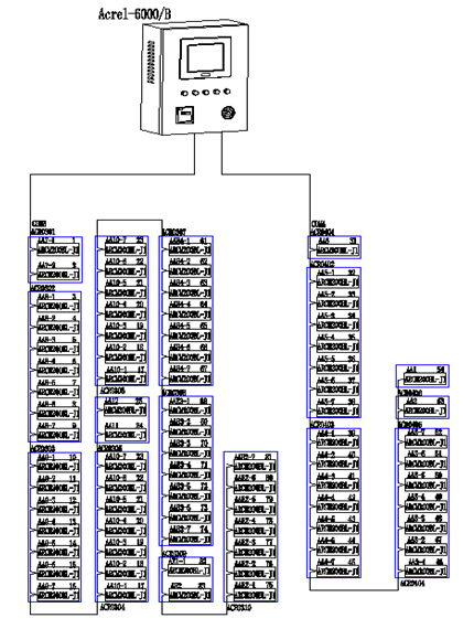
Electrical fire monitoring system topology
3.1 Station management
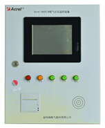
The management of the station control management system for the electrical fire monitoring system is the direct window of human-computer interaction and the uppermost part of the system. The Encore Electric Fire Monitoring System mainframe fully takes into account the user's operating habits and continuous and stable operation, with reference to the corresponding national standards and specifications. The host computer is mainly composed of monitoring software, touch screen, UPS power supply, printer and other equipment. The various types of data information on the site are calculated, analyzed, and processed, and reacted to the terminal management personnel in the form of graphics, digital display, sound, and indicator lights. Enables managers to grasp system dynamics in real time, and realizes functions such as fault information can be traced and information can be exported.
In view of the instrument point and the amount of data in this project, the Acrylic-Acrel-6000/B host is now configured for the project. The specific parameters of this host are described below.
3.2 Network communication layer
All instruments in this project must be connected in strict accordance with the hand, and all communication buses must be laid along the weak bridge. The instruments of this project are distributed in the power distribution cabinets on the floor.
The data bus of this project is designed as two buses. The independent bus facilitates the maintenance of the later system. When a leakage current alarm occurs, the fault circuit can be quickly located according to the checklist provided by us in the later stage to quickly eliminate the fault.
The on-site electrical fire detectors are connected by hand in a twisted pair (ZR-RVSP2*1.0), and the number of meters per bus is about 35.
3.3 Field device layer
In this project, the Ankerui embedded electrical fire detector is installed for the incoming circuit of the floor distribution box. The embedded electric fire detector monitors the leakage current of the distribution circuit in real time to display the working status of the entire distribution system. .
The ARCM series residual current type electrical fire monitoring detector is designed for TT and TN systems below 0.4kV. It monitors and manages the fire risk parameters such as residual current, wire temperature, over current and over voltage of the distribution circuit. Thereby preventing the occurrence of electrical fires and real-time monitoring of various power parameters, providing accurate data for energy management. The product adopts advanced microcontroller technology, with high integration, small size, convenient installation, intelligent, digital and networked. It is an ideal choice for building electrical fire prevention monitoring and system insulation aging prediction. The product complies with the standard requirements of GB14287.2-2005 "Electrical Fire Monitoring System Part 2: Residual Current Electrical Fire Monitoring Detector".
4 system characteristics and working principle
In view of the scale of the project, the actual situation of the project electrical fire detection points. Whether in the terminal residual current detector or the background host is designed according to the actual situation of the project.
4.1 The system characteristics of this project can be summarized as follows:
4.1.1 The terminal detector uses embedded electrical fire detector to facilitate installation, save cost and facilitate post-maintenance.
4.1.2 RS485 bus connection is convenient and operability is strong. When the bus is routed, it is a weak bridge, which is not affected by strong electricity, ensuring stable communication of the entire system.
4.1.3 Taking into account the amount of instrument data in this project, customer requirements. The host of this project is wall-mounted. The wall-mounted host has a simple interface and is easy to operate. It is suitable for the distribution room environment and customer related operation requirements in this project.
4.2 Working principle of electrical fire system
4.2.1 The residual current measurement is based on Kirchhoff's current law: at the same time, the sum of the current vectors flowing into and out of a node in the circuit is zero. Taking the TN-S system as an example, A/B/C/N is simultaneously passed through the residual current transformer. When there is no leakage in the system, the current vector sum of the residual current transformer flowing into and out is zero. At this time, the residual current The secondary current induced by the transformer is also 0; when a relatively large earth leakage occurs, the current vector sum of the current transformer flowing into and out of the residual current is no longer zero, and its magnitude is equal to the current flowing from the earth, that is, the leakage current. The leakage signal is transmitted to the electrical fire detector through the secondary wiring of the residual current transformer, and is sent to the CPU after operation amplification, A/D conversion, and after a series of algorithms, the amplitude of the change is analyzed and judged, and The alarm set value is compared. If the set value is exceeded, an audible and visual alarm signal is sent and sent to the background electrical fire monitoring device.
4.2.2 The terminal detector is responsible for monitoring the residual current value of each loop and transmitting the data of the residual current value to the system host. The terminal detector is also responsible for the real-time display of the residual current value of the monitoring circuit, and can set the limit value. When the residual current value exceeds the limit, it can emit an audible and visual alarm to remind the management personnel to maintain and rectify in time.
4.2.3 The instrument transmits data to the system host through RS485 bus. The system host reflects the running status of the whole system through graphs, reports, event records and other forms.
5 System design considerations and methods
5.1 Electrical fire monitoring system mainly monitors two types of objects, residual current and temperature, and should pay attention to the basic points in design.
5.1.1 About residual current
Since the principle of residual current monitoring uses Kirchhoff's current law, there are certain requirements for the form of the low-voltage power distribution system to be applied. At present, low-voltage power distribution systems that can apply residual current transformers are: TT system, IT system, TN-S system, and cannot be used in TN-C system. For users who will design and install an electrical fire monitoring system, whether it is a new project or an old engineering project, first check the system grounding form of the user's low-voltage power distribution system. Otherwise, design and install the residual current transformer. Detection is simply not possible.
Regarding the AC220V single-phase power supply system, the residual current transformer only needs to cover the L/N power lines, but the neutral line N is not allowed to be grounded again. For the AC380V three-phase power supply system, due to the three-phase three-wire system, three-phase four-wire system, three-phase five-wire system, etc., the residual current transformer is simultaneously sheathed to the A/B/C three-phase power line according to the specific situation. Or cover the A/B/C/N line at the same time. Similarly, the neutral line N is not allowed to be grounded again, and the protection line PE must not pass through the transformer.
When the system grounding type is TN-C type, the industrial automation network must be converted into a TN-S type, TN-CS type or partial TT type system before the residual current detecting device can be installed.
5.1.2 About temperature
Temperature measurement has nothing to do with the form of system grounding. It mainly considers the temperature of key parts of low-voltage power distribution equipment including cables, and is generally applied in secondary protection lines. The temperature probe Pt100 can adopt the contact arrangement method. When the object to be detected is an insulator, the temperature sensor of the detector should be directly disposed on the surface of the object to be detected. When the object to be tested is the temperature change inside the power distribution cabinet, a non-contact arrangement can be adopted, which is close to the heat generating component.
5.2 Point allocation in system design
According to the national standard GB13955-2005 "Residual current action protection device installation and operation" in the provisions of 4.4 on the classification protection, when installing the residual current fire monitoring device, the steps of the point allocation principle are:
5.2.1 Study and analyze the relevant drawings of the controlled low-voltage AC380V/220V distribution line, investigate and verify the distribution of building electrical, and determine the location of the distribution equipment (such as power distribution cabinets, boxes, disks, cables, etc.). Each monitoring detector is assigned to the corresponding power distribution equipment to determine the number of detectors and avoid resetting waste.
5.2.2 Determine the hierarchical protection. In order to reduce the range of power failure caused by the occurrence of personal electric shock accidents and ground faults, three-stage (or two-stage) residual current protection devices of different capacities are usually installed at different locations of the power supply line to form hierarchical protection. According to the power load and line conditions, it is generally divided into two or three levels of protection, suitable for urban and rural first and second level protection.
Among them, important routes should include security, fire, emergency power, channel lighting and important places that do not allow power outages.
5.2.3 In the secondary protection, all the switches shall be equipped with a residual current fire monitoring detector, that is, at the power supply end of the line (first level protection) and the branch head end (second stage also called end protection). Install the residual current detector and connect it to the electrical fire monitoring system for fire monitoring and alarming purposes only.
5.2.4 Temperature detection is based on the basic principle that heat is generated when the power distribution equipment is abnormal.
1) Transformer low-voltage side outlet terminal, transformer body temperature (wind temperature, oil temperature, water temperature) test point, load switch contact.
2) Incoming and outgoing busbar contacts, automatic switch (circuit breaker, knife switch) contacts, large current conductor concentrated parts, and cable docking points of each power distribution cabinet (box).
3) The main joint of the female joint cabinet and the switch contacts of the knife.
4) Compensation capacitor terminal and transfer switch contact.
5.2.5 According to the total number of points installed, select the corresponding wall mount, vertical or piano.
6 System parameter configuration
6.1 Alarm value setting range
The residual current alarm value of the field instrument in this project is set at 300 mA. The setting of the residual current value is detailed in the relevant national standards.
According to the national standard GB14287.2-2005, the alarm value of the residual current type electrical fire monitoring detector is set between 20~1000mA. According to this requirement, the residual current action value at the power supply main line is generally set to 400~800mA, and the residual current action value on the power branch line is set to 100~400mA. Generally, the residual current type electrical fire monitoring detection is set at the actual site. The alarm value of the device shall not be less than 2 times the maximum value of the leakage current during normal operation of the protected electrical circuit and equipment, and not more than 1000 mA. The alarm setting value of the electrical fire detector should take into account the normal leakage current of the power distribution system and the electrical equipment.
6.2 Refer to the cable temperature rise alarm setting reference, according to the "Power Cable Design Specification" for cable temperature requirements
6.2.1 High temperature places above 60 °C should be selected according to the requirements of high temperature and duration and insulation type. Heat-resistant PVC, XLPE or Ethylene-propylene rubber insulation and other heat-resistant cables should be used. Insulated cable. It is not advisable to use ordinary PVC insulated cables in high temperature places.
6.2.2 The ambient temperature of the continuous allowable current carrying capacity of the cable shall be determined according to the multi-year average of the meteorological temperature of the area of ​​use and shall comply with the regulations. When the indoor cable trench is laid, the ambient temperature is the average daily maximum temperature of the hottest month of the site plus 5 °C.
6.2.3 The temperature rise of the cable is related to the laying and heat dissipation conditions.
7 main equipment parameters
The electrical fire monitoring system of the Xinjiang Eighteenth Hospital of the People's Liberation Army consists of the electrical fire monitoring device Acrel-6000/B, the leakage fire detector ARCM200BL-J1, and the leakage current transformer AKH-0.66L. There are not many introductions about instruments and transformers. The relevant information can be found on Ankerui **http:// query.
7.1 main technical parameters
7.1.1 Power supply:
1 rated working voltage AC220V (-15% ~ +10%)
2 Backup power supply: When the main power supply is under voltage or power failure, maintain the monitoring equipment working time ≥ 4 hours
7.1.2 Working system:
24-hour work schedule
7.1.3 Communication method:
RS485 bus communication, Modbus-RTU communication protocol, transmission distance 1.2km, can extend communication transmission distance through repeater
7.1.4 Monitoring capacity:
1 Monitoring equipment can monitor up to 1024 (customized) monitoring units (detectors)
2 can be connected with ARCM series monitoring detector
7.1.5 Monitoring alarm items:
1 Residual current fault (leakage): fault unit attribute (part, type)
2 Temperature alarm (over temperature): Fault unit attribute (part, type)
3 Current fault (overcurrent): Fault unit attribute (part, type)
Monitoring alarm response time: ≤30s
Monitoring alarm sound pressure level (A weighting): ≥70dB/1m
Monitoring alarm light display: red LED indicator, red light alarm signal should be maintained until manual reset
Monitoring alarm sound signal: can be manually eliminated, can be started again when there is alarm signal input again
7.1.6 Fault alarm item:
1 The communication cable between the monitoring device and the detector is open or shorted.
2 Monitoring equipment main power supply undervoltage or power failure
3 The cable between the charger that charges the battery and the battery is broken or shorted.
Fault alarm response time: ≤100s
Monitoring alarm sound pressure level (A weighting): ≥70dB/1m
Monitoring alarm light display: yellow LED indicator, yellow light alarm signal should be kept until troubleshooting
Fault alarm sound signal: can be manually eliminated, can be started again when there is an alarm signal input again
The normal operation of the non-faulty loop is not affected during the fault
7.1.7 Control output:
Alarm control output: 1 set of normally open passive contacts, capacity: AC250V 3A or DC30V 3A
7.1.8 Self-test items:
1 Indicator check: alarm, fault, operation, main power, standby power indicator
2 display check
3 audio device inspection
Self-test time ≤60s
7.1.9 Event Record:
1 Record content: record type, time of occurrence, detector number, area, fault description, can store no less than 20,000 records
2 record query: query according to the date, type and other conditions of the record
7.1.10 Operational Rating:
1 Daily duty class: real-time status monitoring, event record query
2 Monitoring operation level: real-time status monitoring, event record query, detector remote reset, device self-test
3 System management level: real-time status monitoring, event record query, detector remote reset, device self-test, monitoring device system parameter query, monitoring device module detection, operator addition and deletion
7.1.11 Environmental conditions for use:
1 Workplace: Fire control room, manned substation (distribution room), wall on room where someone is on duty
2 Working environment temperature: 0 ° C ~ 40 ° C
3 Working environment relative humidity: 5% ~ 95% RH
4 Altitude: ≤2500m
7.2 basic functions
7.2.1 Monitoring alarm function:
The monitoring equipment can receive the leakage and temperature information of multiple detectors, and emit an audible and visual alarm signal when the alarm occurs. At the same time, the red “alarm†indicator on the device lights up, the display indicates the alarm location and alarm type, and the alarm time is recorded. The sound and light alarm is always maintained. Until the display is reset by pressing the display "Reset" button. The audible alarm signal can also be manually removed using the display "Muffler" button.
7.2.2 Fault alarm function
Communication failure alarm: When a communication failure occurs between the monitoring device and any of the connected detectors, the corresponding detector in the monitoring screen displays a fault indication, and the yellow “fault†indicator on the device lights up, and a fault alarm sound is emitted. .
Power failure alarm: When the main power or backup power fails, the monitoring device also emits an audible and visual alarm signal and displays the fault information. You can enter the corresponding interface to view the detailed information and release the alarm sound. Hardware Business Network Information Center)http://news.chinawj.com.cn
Tinted Float Glass is produced by the float process with the addition of small quantities of metal oxides to color the normal clear glass mix. The visible light reflectance will be even slightly higher than clear glass. Noval Glass has strict tolerances on its colored glass and ensures through precise quality control that the Tinted Glass it makes is the same within a batch and across batches-year after year. Reflective Glass is on-line coated Float Glass which has been carefully designed to meet the twin requirements of architects, the functional and the aesthetic. It is produced using CVD technology that creates a perfectly uniform layer of metal oxide chemically bonded to the surface of the glass. The coating imparts a "mirror-like" facade to the Reflective Glass, giving it visual appeal while providing functional benefits like solar control and glare reduction. As this hard chemical layer is fully banded to the glass, the glass can be cut, bent, tempered, heat strengthened and laminated without affecting the coating.
Colored Float Glass,Coloured Float Glass,Black Float Glass,White Float Glass
Jinan Coton Glass Co., Ltd , https://www.cotonglass.com