Figure 1 shows the forged piece of the 31316/02 from a straight design to a contoured shape with a contoured cone angle of about 30. If such products are formed and expanded, the flow line of the raceway is close to the finished product, which not only improves the material utilization rate, but also effectively improves the contact fatigue strength of the bearing.
1. Process plan determination and difficult analysis
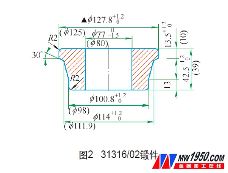
(1) Drawing the forgings Figure 31316/02 The tolerances refer to the current standard, the outer diameter is 2.8+1.2+0, and the inner diameter is 3-0--1.5. To compensate for the possible end defects, the height is appropriately enlarged. 3.5+1.2+0, as shown in Figure 2.
(2) Analysis of processing difficulties During the expansion process, the rolling wheel expands the ring blank with pressure F under the action of the liquid pressure of the D51Y-250E reaming machine. The forgings are relatively thick and long in the radial direction, the metal flows in the circumferential direction, and the inner and outer diameters simultaneously expand. The outer tapered toe has an axial cross-sectional area that is different, and a component force is generated at the slope, so that the local deformation force is reduced and the deformation is difficult. As shown in Fig. 3, the deformation component of the slope from the rolling wheel causes the billet to be thinned, and the other component has a tendency to move the billet toward the small end face (where α is the taper angle of the outer taper forging).
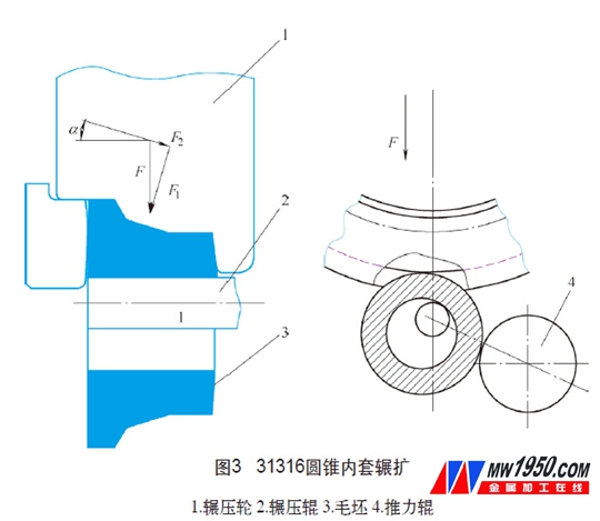
The larger α, the smaller the F1 and the more difficult the deformation. The ability of the reaming machine to distribute metal there is weakened, so it is necessary to ensure that the cross-sections are reasonable when making the blank. The wall of the small end face is the thinnest, the most easily plastically deformed, and the axial burr occurs with the expansion. The wall of the large end face is the thickest, and the surface deformation caused by the expansion force is not easily transmitted to the center of the blank, and the concave core is easily formed.
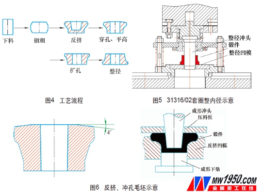
(3) The process route is determined as shown in Fig. 4. In order to ensure the size of the forging, the inner diameter taper is corrected, and the full diameter step is added after the hole is expanded.
2. Solution
(1) The process key point process guarantees the expansion ratio of 1.3~1.8, and under the premise of ensuring the strength of the pressure roller, the expansion ratio is appropriately increased, and the f 45mm standard punch is selected.
The forging temperature is controlled to prevent over-temperature, and the blank is not allowed to stay at room temperature for too long, and the enthalpy is expanded between 800 and 1100 ° C in the optimum plastic deformation temperature region.
To ensure the performance requirements of the equipment, it is not allowed to excessively move the rolling wheel and the thrust roller to cause the rib size to be out of tolerance (see Figure 5).
(2) Mold preparation According to the law of equal section, calculate the blank size of each section of the forging, complete the “first†dosing of the forging, and focus on the control of the “back-squeeze†of the blank quality, design the semi-closed forming die, and the blank is mostly In the die, the upper part of the large rib is freely deformed. The end face is flattened, and the lower surface is processed into a slope shape (generally 3°~5°), so that the final blank shape is as shown in Fig. 6. When the ram is expanded, the blank is gradually filled with the pressing wheel cavity, which effectively prevents the concave end of the end surface.
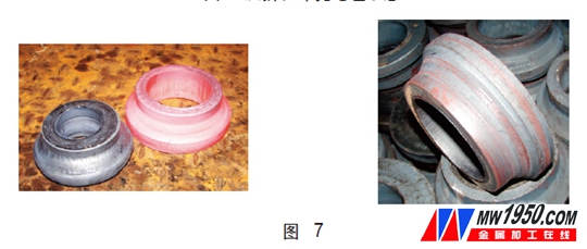
3. Production effect
As shown in Figure 7, after the trial production, the 31316/02 forging blanks and finished product dimensions and technical requirements are in line with the process and the appearance quality is good.
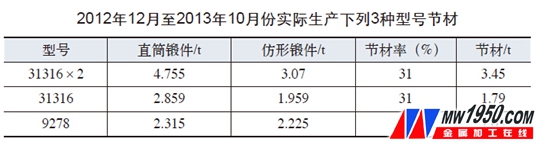
Our unit has another 9278, 31316X2/02 two-piece large cone angle forgings put into production. The relevant numerical statistics are shown in the attached table.
It can be seen from the above table that from December 2012 to October 2013, a total of three models were produced, and the material saving rate was over 30%. A total of 6.2 tons of bearing steel was saved, and the economic benefits were remarkable.
About the author: Liu Zhenwei, Wang Yujie, Wang Zhanye, Luoyang LYC Bearing Co., Ltd. Forging Factory.
Suitable for different soil types
Cost saving and Saving time
Short assembly time and Quick mounting
Immediately loadable and Quick changes of position
HD Model 20,for installing Ground Screw sizing of 76x1200mm or smaller ;mainly applied for mounting garden fences, safety fences, traffic sign post and advertising boards.HD Model 30 and Model 50,for installing ground screw sizing of 89x2000mm or smaller ;mainly applied for solar farm construction, carports, flagpoles, sun shading ,wooden houses and playground facilities.
This Electric ground screw drivers are designed to install or remove various sizes and types of ground screws.This driver is shipped completely assemble.There is a reverser on the handle of host machine.When we push the reverser,the host machine will contrarotate,Then ground screw will be drilled out.When the ground screw work normally,the adjusting knob of control instrument can be adjusted to maximun.It can ensure the host machine output the biggest torque.
features
1,high quality ground screw electric-driver
2,easy and fast install
Electric Screw driver
Mini Screw Driver,Ground Screw Driver,Electric Screw driver
Hebei Honde Plastic & Metal Co., Ltd. , https://www.foundation-system.com